A site for solving at least some of your technical problems...

RJ45 and crossover cable
Submitted by Alexis Wilke on Sat, 03/15/2014 - 15:27
Basics
I got a cross over CAT6 cable and somehow the computers on which I used it do not like it...
So I thought maybe it was not a valid crossover cable. After all, it would not be the first time I buy some hardware which is not exactly what it was advertised as being.
The following are a few pictures that give us the answer, though. You have to look for the colors of the wires in the RJ45. It's not very easy to see, but it is different enough (assuming you are not color blind... sorry if you are, you probably will have to test with a device or a battery and an LED or light bulb) that you should be able to tell exactly.
Note that now I know why it didn't work for me. The second port of the network card of one of the computers was blown up. This is why the computers "did not like it". Some of the electronics was broken. As a result, also, that second port runs at only 100Mb instead of the expected 1Gbps. That's the second computer I have had that has a broken onboard NIC. Oh well...
What is the purpose of a Crossover Cable?
First you may wonder why someone would want a crossover cable.
There is a normal network setup. You have 2 or more computers and to connect them together, you connect their network card to a switch or a hub.
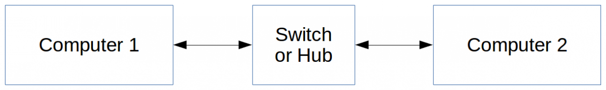
This works as is.
Now there are cases where you may want to connect two computers between each others, directly, as follow:
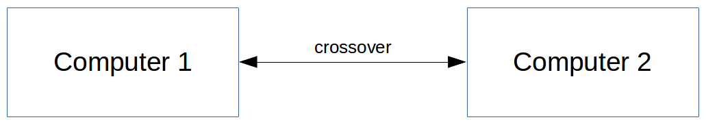
This is why you would need a crossover cable.
You see, in the old days, network cards were not capable of automatically switching their TX and RX pins. Today, 99.9% of the new cards do that automatically. In other words, today you pretty much never need a crossover cable (even though they are still available for sale, even in CAT6.)
The reason for the requirement is that electornically, trying to connect the TX on another card's TX (and the RX to the other card RX) would not do anything. More or less nothing could be sent or received. For that purpose we created what was called crossover cables. These would have the TX and RX wires swapped on one end of the cable so you could directly connect two computer network cards with a cable (instead of having to go through a switch or a hub as normally done in a network system.) The result was that the TX would send data to the RX of the other card, as expected.
What was the Uplink of a switch used for?
Actually that brings up the Upling connector at times seen on switches. Similarly, the TX and RX lines of a switch could be automatically be switched. Because of that, the switch needed an Uplink if you wanted to connect it to another switch regular port. That Uplink connector would have the TX and RX in the same place as a computer network card and that made it possible to connect that switch to another and thus create a larger network.
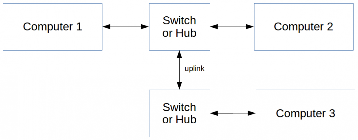
Now it's rarer to see an Uplink connection on your switch since it is not required. You can connect any switch with any other switch and still get the same functionality. The TX and RX lines will automatically be swapped on one of the switches, just like in a network card.
The Red (Orange) Cable
 Now, I wanted to make sure that I purchased a crossover cable. I needed a way to be able to distinguish such a cable from a normal (a.k.a. "straight-through") cable.
The easiest way to tell whether a cable is a crossover cable is by looking for the red (at times, orange) cable. I'm not too sure what why that cable is at times red and other times orange. If I find out, I'll add the info on this page.
If the red cable is close to the edge in one RJ45 and further away from the edge (i.e. closer to the center) on the other, then you have a crossover cable.
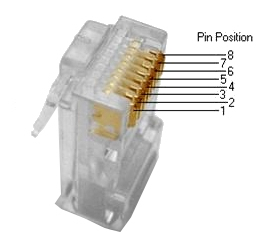
First there is a picture of an RJ45 pins with numbers. That is important to determine where pin number 1 is.
Place that plastic part that holds your cable in an RJ45 socket at the top. Pin number one is on the left side. Now we can move on with the more theory like pictures of an RJ45 cable.
RJ45 Crossover Cabling
The following picture shows the colors of the cables wired on those pins.
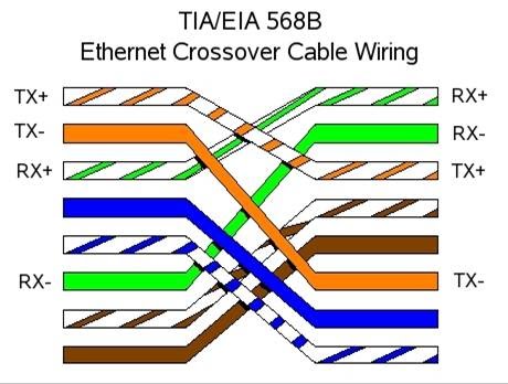
This figure shows the cabling of a crossover RJ45 cable or jack (they now sell jacks that do the crossover for you!)
So, just like with a serial cable, you swap the transmit and receive cables. That way the TX (transmit) on one ends, ends up on the RX (receive) at the other end and vice versa.
In a switch or a hub, that cross over is in the device itself. This is why they used to offer an Uplink on switches. In other words, it's not that a switch could automatically switch its TX and RX cables, instead, it was on purpose wired crossed to accept a straight cable.
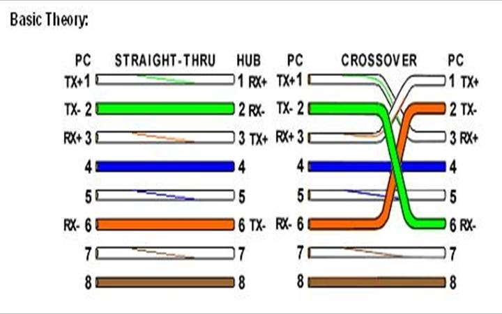 This last picture shows you the difference between a straight through cable which ou connect to a switch or a hub and a cross over cable used to connect two PCs to each others. As you can see the red or orange wire has a quite different position in both RJ45 jacks if you have a crossover. You should be able to see that wire in the translucid Jack.
Source: I found the RJ45 images on What is the defference between Cross Cable and Straight Cable.
Recent Posts on The Linux Page: